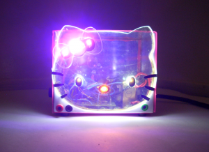
 The Hello Kitty Power Supply project was for a Mechatronics class I took, MECH 14 Fabrication Techniques. The first step in a project like this was to understand how a power supply works. Through the process of reviewing the electronic schematics of a linear power supply I came to understand how the device functioned. Then a hand drawn layout of all the components as they will reside on the Printed Circuit Board (PCB) took place. Everyone in the class then created a unique version of the schematic diagram utilizing a piece of software called Circuitmaker. To make the PCB, all of the components that were created in Circuitmaker get exported to a similar program called Traxmaker. Within Traxmaker the different layers that make up the PCB come together, the software does a great job of automatically routing the traces. A netlist is used to provide an extra level of assurance in order to verify that both designs function in the same manner. Netlists are no more than a text document which lists all of the components and all of the individual points that they connect to. Once the whole class had completed their designs the files were assembled into a single Gerber file, which was then sent to a manufacturer in Asia for production.
With the internal design complete, the focus shifted to the enclosure. This is where my own personal learning curve got steeper through introspection. What did I honestly want out of this project? I was told that it is something I should be proud to take on a job interview or, at a minimum be happy with it sitting on a shelf at home. I settled on making a Hello Kitty-themed power supply after a quick search of the internet yielded no officially licensed Hello Kitty Power Supply™.
The first step was to take the iconic image of Hello Kitty and to enlarge it. From there the shapes of the two main pieces, the face and hair bow were transferred to a piece of plexiglass. Using a upright band saw, multiple pieces of each shape were cut to allow for variations that may cause an individual piece to be appear to be a better fit than others. With a physical Hello Kitty face in hand I was able to use a manila hanging file to create a mock-up chassis. This layout process allowed me to ensure that all of the pieces would physically fit together with enough room for assembly.
With a flimsy conceptualization of what was to be constructed, a piece of graph paper was used to help gain a better perspective of the final dimensions. With all of the bend allowances accounted for I made 10 measurements before finally making my first cut. Once the chassis were cut out, the holes were drilled and the edges got bent, followed by the front and back panels being bent. Holes were drilled into the plexiglass to allow for the LEDs to have half of their lense recessed as a way to better diffuse the light across Hello Kitty’s face. The top and bottom of the chassis were both wrapped in hot pink vinyl which makes the power supply look like it is a molded plastic, giving it that true Hello-Kitty-made-in China-look.
Throughout the fabrication process I was not sure how to approach a certain aspect, but I was able to always find someone that was willing to walk me through the problem. If I was to do one thing differently I would have not taken MECH 14 and MECH 44 during the same semester. The fabrication techniques I have learned in both MECH 14 and MECH 44 have helped me take my fabrication skills to the next level. Hello Kitty has yet to contact me about a licensing agreement ( nor to tell me to cease and desist). While I have no problem getting compliments on this project, I have only used it a handful of times as I am more likely to grab a switched mode wall wart power adapter and cut off its connector. I find the paradox I created to be quite interesting, crafting something so aesthetically pleasing that it loses its functionality.
